Rotor casting procedure
Before starting, check that everything is ready:
• the moulds are prepared with polish or release agent,
• the magnets and the magnet disks are clean and bright (no grease),
• 16 strips of CSM are ready to fit between the magnets
• the stainless steel wire is cut to length and taped
• the magnet positioning jig is ready
The amounts of resin mentioned in this procedure are enough for two magnet rotors.
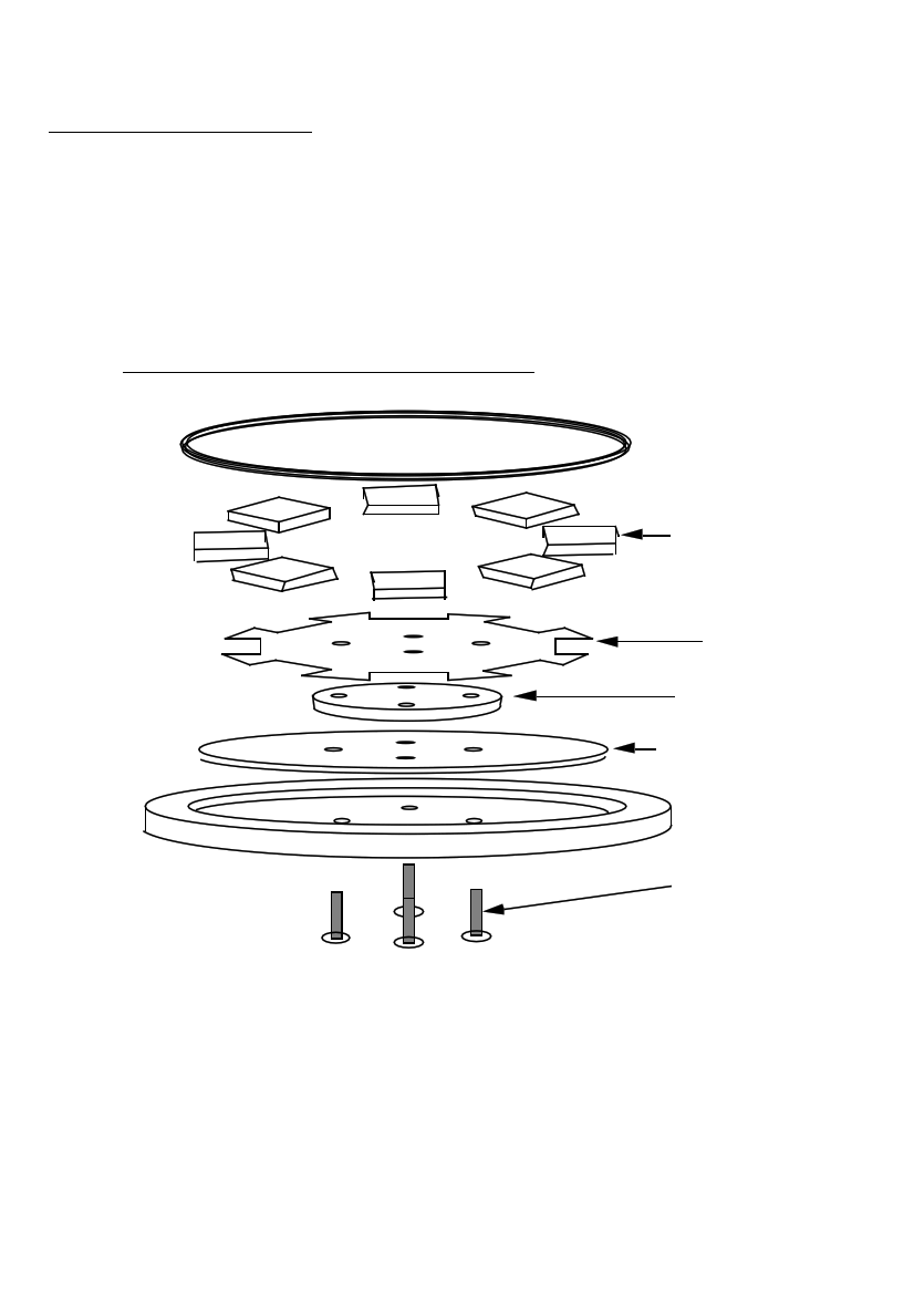
37. MAGNET ROTOR MOULD ASSEMBLY
STAINLESS
STEEL WIRE
MAGNETS
JIG
MOULD
STEEL DISK
MOULD
FOUR BOLTS
• Place four bolts through the holes in the outer mould, from below (see diagram
37). Lay a steel disk in the outer mould. Place the inner mould on top. Check the
taper, and place the smaller face down, so that it can be easily removed after
casting.
• Mix 200g of resin with 3cc catalyst. Paint it all over the steel disk. Add 20g of
pigment for colour if required. Mix 100g talcum powder with the remains of the
PMG manual
page 34
June 2001